-40%
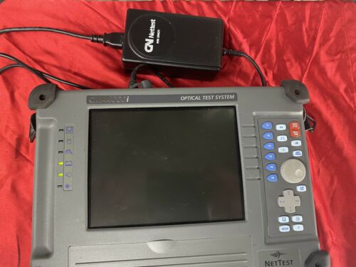
CN Nettest CMA4000i CMA4453M; CMA4000i Optical Test System W/Lots of Extras
$ 554.4
- Description
- Size Guide
Description
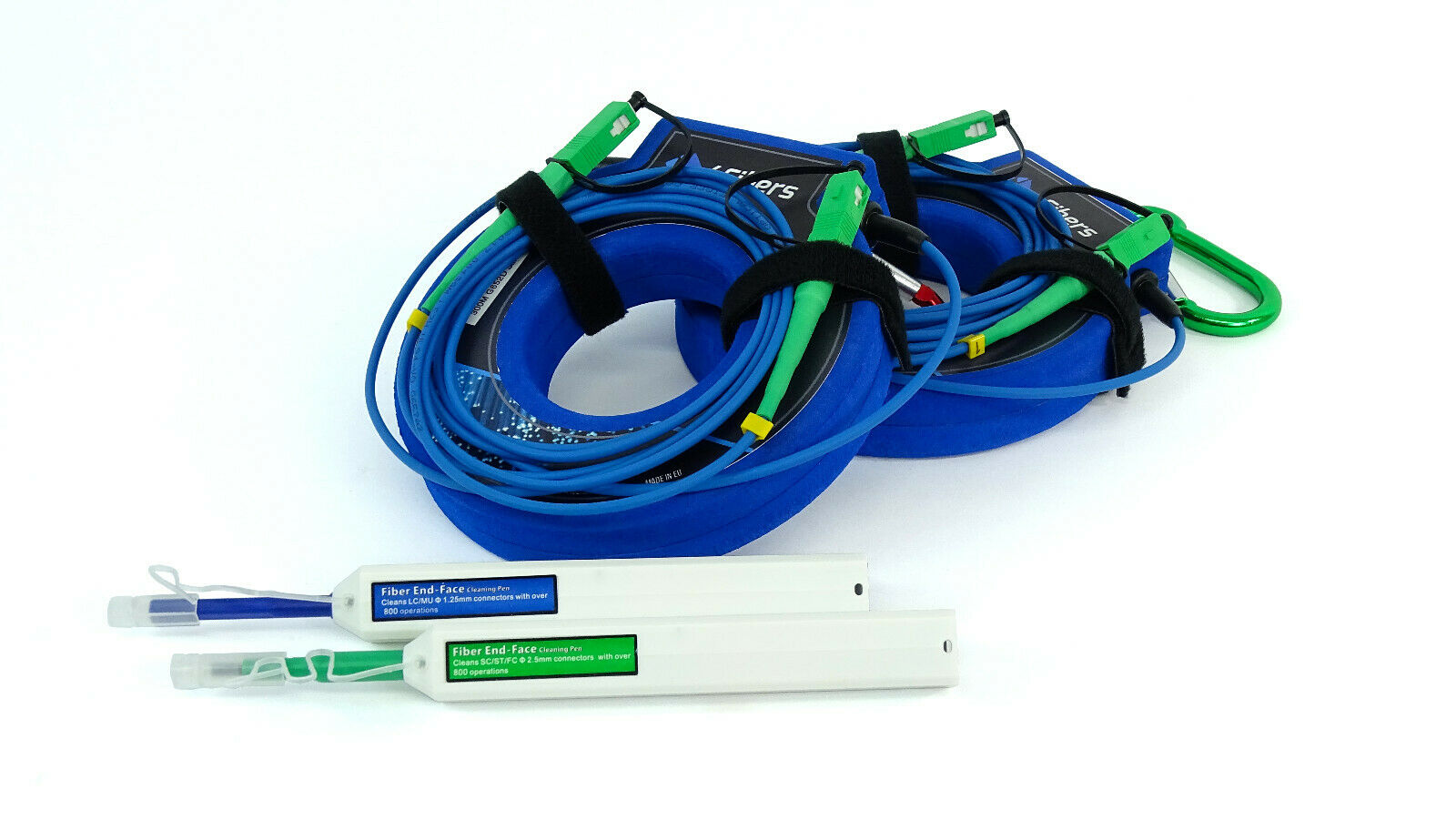
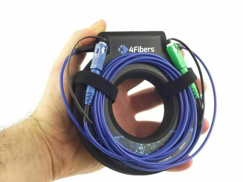
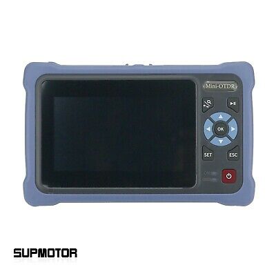
CN Nettest CMA4000i CMA4453M; CMA4000i Optical Test System W/Lots of ExtrasSee pictures. All original equipment in own Riad case.
Powers up. And navigates thru windows. No further tests applied.
CMA4000i OTDR Mainframe
The CMA 4000i Optical Test System provides the most complete test and measurement solution for the All-Optical Network. With its modular design, the instrument can be configured to meet the most demanding requirements for a variety of applications from fault location to testing Dense Wavelength Division Multiplexing (DWDM) systems. The CMA 4000i can be configured as an OTDR with a Visual Fault Locator, Optical Power Meter, and Light Source; or as a high resolution Optical Spectrum Analyzer (OSA) for DWDM systems. With its variety of functions, the CMA 4000i offers the best value for optical network commissioning, troubleshooting, restoration, and maintenance applications.
Applications
CMA 4000i is the all-in-one test system for qualifying optical networks:
Commissioning
Fault Location / Restoration
Maintenance
DWDM System Turn-up
The Industry Leader in Optical Performance
High performance networks demand even higher performance test and measurement equipment -- and there’s no better solution than Anritsu's award winning test and measurement solutions. The CMA 4000i continues the Anritsu tradition of worldwide leadership in optical test and measurement.
With 50 dB of dynamic range and deadzones as small as 3.0 m, the CMA 4000i is ideal for testing long haul backbone networks, metro networks, or Passive Optical Networks (PONs). For complete system characterization, the CMA 4000i can easily be equipped with a light source and power meter for complete end-to-end loss testing. In addition, its Visual Fault Locator (VFL) option enables you to locate breaks within the OTDR’s deadzone or identify specific optical fibers within a cable. The 4000i offers a variety of operating modes for varying OTDR applications.
DWDM System Qualification
For commissioning or maintaining networks that employ DWDM technology, the model 4792 OSA module for the CMA 4000i is the ideal instrument. It allows testing both current and future DWDM networks. Operating from 1520-1620 nm (C- and L-bands), the model 4792 OSA module can automatically identify over 400 DWDM channels spaced less than 12.5 GHz apart -- perfect for testing high capacity DWDM systems.
Characterizing complex DWDM systems is simple with the CMA 4000i. One-button operation ensures that even the novice user is capable of characterizing a complex DWDM system for channel center wavelength, power, and OSNR. Simply power on the unit with the OSA module installed to see one of the following views: Table View, Drift View, or Graph View.
Features
Highest Dynamic Range in the industry: 50 dB
OTDR, Loss Test Set, and VFL in a single module
Optical Spectrum Analyzer module with 10 GHz channel resolution
One-button testing
Operating Modes
Fault Locate Mode With its one-button auto test option, the CMA 4000i brings ease of use to a new level. Simply attach the fiber to the instrument, press Fault Locate, and your entire fiber optic cable is completely characterized for attenuation, splice loss, and reflectance. For users needing more measurement flexibility, the CMA 4000i offers the following modes to bring OTDR testing to a higher level:
Construction OTDR Mode Construction Mode simplifies and automates the tests and documentation most frequently performed during fiber installation. Construction Mode is designed for testing multiple fibers, and is ideal for cable installation and commissioning. It eliminates the time consuming setups common to the repetitive practices of testing, storing, analyzing, and documenting high fiber count cables.
From the setup screen, the operator can quickly select one or all wavelengths to test, specify the file naming structure, and enter the fiber count for a given cable. Once set up, the OTDR acts as a “task master” to perform the following functions:
Select the wavelengths
Test the fiber at all selected wavelengths
Analyze the trace data
Store the trace and analysis data to either floppy or hard drive
Alert the technician to move to the next fiber to be tested and increment the filename to the next sequential number
Expert OTDR Mode Expert OTDR allows the user to perform traditional OTDR functions with dedicated hard keys tied to frequently used OTDR parameters such as pulse width, range/resolution, and wavelength. This mode provides unsurpassed user flexibility for optimization of OTDR parameters without stopping the test in progress. Key features of the Expert Mode include:
Real-time Testing
Splice Optimization
Loss Mode Setup
Dual Wavelength Testing
Trace Compare Mode
Trace Shift Capability
Views
Table View Table view is ideal for quickly characterizing a DWDM system’s essential features and performance. The number of channels, channel spacing, and relative power between channels is immediately visible. The table also shows each channel’s wavelength/frequency, power, optical signal-to-noise ratio (OSNR), delta wavelength, and delta power.
Graph View Graph view displays full spectrum data and allows full manipulation of the waveform. Since this view displays the entire spectrum at all times, the user can zoom in while still maintaining a full spectrum view. In addition, it allows acquired and recalled data to be displayed together; this is especially useful for comparing spectra, analyzing channel power flatness, and viewing channel spacing.
Drift View Drift view is used in conjunction with the drift acquisition mode and is ideal for evaluating long-term power and wavelength stability of DWDM channels. This view displays channel number, reference wavelength, reference channel width, current wavelength, current power, minimum/maximum detected wavelength, and detected power. It can also be used to compare the received channel frequencies to the ITU standard DWDM grid or to a user-defined template, making field procedures simpler than ever.
Mainframe Specifications
Display VGA LCD Display (21.3 cm (8.4 inch) color or 20.8 cm (8.2 inch) monochrome)
Floppy Drive 3.5 inch/1.44 MB floppy disk
(up to 180 OTDR traces for a standard disk)
Keyboard Intergral alpha-numeric, external keyboard (optional)
I/O Ports Standard: (2) RS-232 Serial, (1) Parallel, VGA, Mouse, and (1) PS/2 External Keyboard Port
Internal Storage Up to 125 OTDR traces internal
2 Gigabytes minimum (Over 65,000 traces with hard drive option)
Dimensions (H x W x D) 24.1 x 34.3 x 9.5 cm (9.5 x 13.5 x 3.75 inches)
Weight 4.9 kg (11.0 lbs.) Includes mainframe, battery and module
Power Supply Autoswitching 100-132 VAC, 47-63 Hz, 184-250 VAC, 47-63 Hz, 10-15 VDC
Battery (2) Sealed lead acid battery pack
Battery Life 6 hours typical, depending on operating mode
Recharge Time 1.5 - 2 hours
AC Power Temperature 0º C to 45º C (32º F to 122º F)
AC Power Humidity 95% RH max., non-condensing
AC Power Maximum Altitude 15,240 meters (50,000 feet)
Battery Temperature 0º C to 40º C (32º F to 104º F)
Battery Humidity 95% RH max., non-condensing
Battery Maximum Altitude 15,240 meters (50,000 feet)
Storage Temperature -25º C to 60º C (-13º F to 140º F)
Storage Humidity 95% RH max., non-condensing
Storage Maximum Altitude 15,240 meters (50,000 feet)
CMA4415 SPECIFICATIONS
Form Factor Module (proprietary interface/bus)
Fiber Type Singlemode
Minimum Wavelength 1310 nm
Maximum Wavelength 1550 nm
Maximum Distance Range 256 km
Minimum Distance Resolution 0.1 m
Maximum Distance Resolution 0.16 m
Maximum Dynamic Range 28 dB
Dead zone distance 3 m
Minimum Pulse Width 10 ns
Maximum Pulse Width 10 us
Connector type (main signal)
FC/SPC
